Showing posts with label FC0012. Show all posts

2013-05-29

Naked hardware #8: Cabletech URZ0185

About the device

That device is Afatech AF9035 reference design. It has two independent tuners aka dual tuner model. Used RF tuners are Fitipower FC0012. Device uses chipset vendor reference design USB ID 15a4:1001.

I would not like to thank device vendor Cabletech as they didn't even answered my queries about sample device. Instead thanks to some anonymous Linux user who donates his device for driver development.

Device is supported under Linux starting from the Kernel 3.9.

Cabletech URZ0185 teardown

Cabletech URZ0185

Key components:

Afatech AF9035
Afatech AF9033
Fitipower FC0012

PCB top side

AF9035 and AF9033
All relevant chips are composed to that side of the PCB. Two chips, which are partially under piece of tape and located near antenna connector, are FC0012 RF-tuners. There is two RF-tuners as this device supports dual mode - it could receive two television channel at the time even those channels are delivered using different frequency.
Black component, which is partially top of both tuners, is IR-receiver for remote controller. Piece of tape between RF-tuner and IR-receiver is avoiding possible short circuit(?).
Black chip most near USB-connector is AF9035. I am not going to AF9035 details now as I have explained it quite carefully earlier. Lets still mention it is chip that integrates USB-interface and DVB-T demodulator. Demodulator integrated is AF9033. That version of AF9035 has also pins to connect slave demodulator using serial TS.
There is small metal box, crystal, between AF9035 and USB-connector. It offers 12.000 MHz clock source for AF9035. 12.000 MHz is very standard USB reference clock.
The most centre big chip is AF9033 DVB-T demodulator. It is slave demodulator for AF9035 offering 2nd tuner. Note that AF9035 itself integrates one AF9033 - so there is two AF9033 logically on that device. AF9033 gets clock from AF9035, own crystal is not needed for that kind of dual configuration. There is clearly visible 4 + 2 wires between AF9033 and AF9035. That four wire bus, going through resistor network RP1, is most likely serial TS. Two wires going through resistors R23 / R24 is likely I2C bus. TS bus feeds data and I2C is used for control.
IR-receiver is connected to AF9035. First FC0012 is connected to the AF9035 and second one to AF9033, both TS and I2C buses.

RF-tuners

FC0012 tuners
FC0012 tuner is based of direct-conversion architecture. From that picture it could be easily seen 4-wires going from both tuners to AF9033/AF9035. It is baseband (aka Zero-IF) interface to feed signal from tuner to demodulator. There is also I2C bus between each demodulator and tuner pair, but it is not easily visible. 36.000 MHz clock is feed from the crystal that is located another side of PCB. Only one crystal is needed as tuner has clock bypass. RF-input, antenna wire, is also bypassed from tuner to other.

PCB bottom side


Bottom side of PCB
That side of PCB is quite empty and boring. The only and the one 8 pin IC is  2k serial eeprom. Markings are not clearly visible, but looks like letters are "402RP", which I could guess is 24C02RP. Eeprom is used to tell device hardware confguration for AF9035. Content is read by AF9035 on startup.
36.000 MHz crystal is for FC0012 RF-tuners.
PCB has printings "94-V0", "12-13", "DK-5902 V1.0", "iTE Technologies, Inc". Last one reveals it is clearly reference design. Originally AF9035 was made by Afatech and later Afatech was acquired by ITE Technologies.

Block diagram
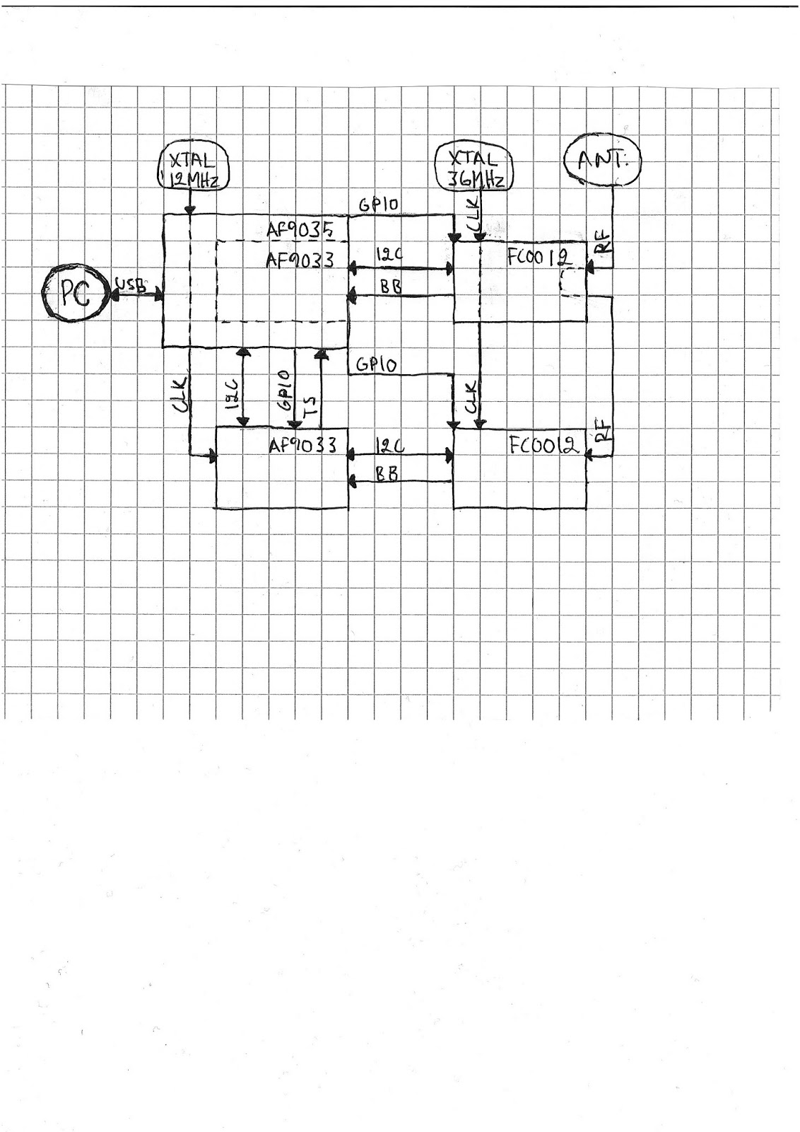
AF9035 FC0012 dual tuner block diagram
I had very much troubles in order to get that device working! That was due to very complex hardware configuration. Because of dual tuner support it has physically 4 chips and logically even one more (AF9035 integrates AF9033). There was existing drivers for all the used chips, so it was "only" tweaking correct setup. Most problematic things were tuner clock bypassing, tuner RF bypassing and GPIOs. I took quite many USB sniffs, made scripts to generate code and hundreds of trial and error tests. After all that intensive reverse-engineering, I decided to write block to visualize relevant connections. For all the other AF9035 dual mode devices you could expect pretty much same.
It took something like 60 hours of work and result was only about 100 lines of code. Sometimes Kernel coding is very slow at the unit of used hours for lines of code, especially when hacking with complex embedded hardware.


USB interface

IDLE current drain without a driver: 183mA


Pictures


2013-05-26

Naked hardware #7: TerraTec Cinergy T Stick Black

TerraTec Cinergy T Stick Black teardown

That stick is Realtek RTL2832U reference design. Used RF tuner is Fitipower FC0012. TerraTec has assigned USB ID 0ccd:00a9 for that device.

Device is supported under Linux starting from the Kernel 3.6.

TerraTec Cinergy T Stick Black

TerraTec Cinergy T Stick Black


Key components:

Realtek RTL2832U
Fitipower FC0012


PCB top side

Top side of PCB
Both main chips are that side of the PCB. Upper one is FC0012 RF-tuner and lower one is RTL2832U demodulator & USB-interface. Naturally, RF-tuner is near antenna connector and USB-interface chip is near USB connector. There is 28.800MHz crystal quite between the chips. It is that clearly visible metal box. It offers clock source for both RTL2832U and FC0012 - saving one crystal.

Black box, right side of PCB and near antenna connector and FC0012, is IR-receiver for remote controller.

FC0012 is direct-conversion (aka Zero-IF) architecture RF-tuner. It is very typical DVB-T RF-tuner what we could expect to see nowadays. There is four clearly visible parallel wires between FC0012 and RTL2832U, which are going through SMD resistors, that are located very near FC0012. It is baseband interface, I+, I-, Q+, Q-. That bus feeds baseband "antenna" signal from tuner to demodulator.

I am not going to explain RTL2832U features that time as I have explained those earlier. Please see older blog posts.


PCB bottom side

Bottom side of PCB
That side of PCB is quite empty and booring. The only and the one IC, marked as FM24C02A, is 2k serial eeprom. As usually it contains configuration information for RTL2832U, most notably TerraTec own USB ID.

USB interface

IDLE current drain without a driver: 18mA


Pictures