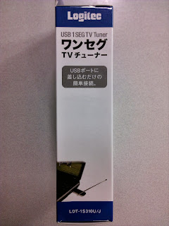
Logitec LDT-1S310U/J teardown!
It is Mirics MSi3101 reference design and nothing more. |
| Logitec LDT-1S310U/J |
Key components:
Mirics MSi2500Mirics MSi001
General info
First of all, check my earlier post about Mirics MSi3101 Linux driver as that device is similar from the hardware point of view. Device is sold as a 1seg ISDB-T TV tuner for Japan market. 1seg aka One Seg is mobile digital television standard used in few countries like Japan and Brazil. Only thing that makes this device as 1seg receiver is bundled software. As a SDR based DTV solution it is possible to use same hardware for receiving other standards just using another software.Device has no eeprom, which means USB ID is the one defined by chipset itself 1df7:2500 (chipset default ID). That means it is compatible with all software released for Mirics MSi3101.
Initial Linux support for that device has gone to the Kernel 3.12 as a staging quality.
Hardware internals
 |
| PCB top side |
PCB is rather tiny, only 37 x 17 mm. MSi2500 is integrated USB interface ADC. MSi001 is silicon RF tuner. I am not going to chip details now as I have done it earlier, just look my older blog posts about MSi3101 for more detailed information.
Antenna connector looks like typical MCX but it is not. Type of that connector is unknown for me but, fortunately package contains antenna pigtail cable having standard F female on the other end. There is also two small antennas bundled. Other antenna is quite unusual small telescope without a cable and another is typical mini-magnet type, coming along with almost every of these DTV sticks.
PCB has some printings:
LWE 88 94V-0
10510
PCB bottom side is almost empty
 |
| PCB bottom side |
Nothing to say.
PCB printings:
ISDBT2036 Ver 1.0
Connected antennas
 | |
| MSi001 antenna inputs |
VHF (pins 9, 10), BAND3 (pins 3, 4) and BAND45 (pins 6, 7) antennas are connected. AM (pins 37, 38 & 39, 40) and LBAND (pins 24, 25) inputs are not connected. That limits actual frequency range to 50 - 960MHz.
It is possible to connect those unconnected inputs but it is not very trivial as chip is very small. Likely microscope soldering station is needed.


Here is one EU eBay seller, selling just that Logitec device: http://www.ebay.de/itm/281181098268
ReplyDeleteThese early devices can still be seen in many facilities across the country, and many are in good working order and maintained properly. click here
ReplyDeleteAnyone have a lead of sources for this dongle? Maybe a SKU or item number? Can't seem to find any used anywhere.
ReplyDeleteRivals can opt to carry on playing the video game paraskasinotfi.com once they just like the first individual who surfaces and finishes all his cards will acquire along with the video game ends.
ReplyDeleteI would suggest them to anyone possibly starting a business or even looking to develop! york web design agencies
ReplyDeleteWhat are the benefits of a virtual office?
ReplyDeleteNot only do virtual offices allow for no commute time, low to no technology costs and lower overhead costs (with no lease to pay), having remote workers also cuts down on commute time, increases productivity, and produces a lower turnover rate.
Learn MOre
If you are an internet user on daily basis then must checkout this site. It has been an amazing experience. Believe me it’s totally worth of your time. Suggested to everyone! click here
ReplyDeleteThis loan calculator really helped me plan better. https://luurituki.fi/alypuhelimen-rahoitusdilemma-kumpi-kannattaa-valita-liittymasopimus-vai-kulutusluotto/
ReplyDelete